Supply Voltage Monitor Circuit Diagram

A circuit for monitoring supply voltages of ±5 V and ±12 V is readily constructed as shown in the diagram. It is appreciably simpler than the usual monitors that use comparators, and AND gates. The circuit is not intended to indicate the level of the inputs. In normal operation, transistors T1 and T3 must be seen as current sources. The drop across resistors R1 and R2 is 6.3 V (12 –5 –0.7). This means that the current is 6.3mA and this flows through diode D1 when all four voltages are present. However, if for instance, the –5 V line fails, transistor T3 remains on but the base-emitter junction of T2 is no longer biased, so that this transistor is cut off. When this happens, there is no current through D which then goes out.

Supply Voltage Monitor Circuit Diagram

supply voltage monitorw Circuit diagram

Read More

Electronic Fuse for DC Short Circuit Protection

This is an electronic fuse that protects the load against short circuit. Relays must be chosen with a voltage value equals to the input voltage. Don’t omit using the 100uF capacitor with appropriate voltage value with respect to the input voltage. If you can’t provide, you can use C106 instead of BRX46.

 Electronic Fuse for DC Short Circuit Protection

Circuit Project: Electronic Fuse for DC Short Circuit Protection by BRX46


You can adjust the current with using 10K potentiometer. If you will use the fuse with very high currents, lower the 0R6 5W resistor value (ex. 0R47, 0R33, 0R22 or 0R1). Watt value of the resistor should be increased also.
Read More

Voltage Regulators Protector Circuit Diagram

People often forget that many voltage regulator ICs have an upper limit (usually 35 V) on the input voltage they can handle. That applies primarily to types with a fixed output voltage. Adjustable voltage regulators also have a maximum voltage specification, in that case between the input and output (commonly 40 V). The input voltage must thus be limited to that level in a fault situation in which the output is shorted. This circuit shows a way to allow such regulators to be used in situations with higher input voltages. Although the solution consists of an additional three components, it is simple and can be built using commonly available components.

The voltage across the regulator is limited by the combination of T1 and zener diode D1 to a value that allows the regulator to work properly with loads up to the maximum rated load. R1 provides an adequate operating current for D1 and the bias current for T1. It’s a good idea to use a Darlington type for T1 in order to keep the value of R1 reasonably high. The current through D1 is only 10 mA with an input voltage of 60 V. Naturally, we also measured what the circuit does when no load is connected. Surprisingly enough, the nominal output voltage of 5.02 V increased to only 5.10 V (with a 60-V input voltage). In our experiments, we used a BDV65B for T1 and a value of 4.7 kΩ for R1.

 Voltage Regulators Protector Circuit Diagram

Voltage Regulators Protector Circuit Diagram


If you want to ensure that the circuit is truly short-circuit proof with an input voltage of 60 V, you must use a transistor that remains within its safe operating area at the maximum input voltage with the short circuit current of the regulator (which can exceed 2 A). The BDV65B and TIP142 do not meet this requirement. The maximum voltage for the BDV65B is actually 40 V, and for the TIP142 is 50 V. If the transistor breaks down, the regulator will also break down. We verified that experimentally. One possibility is to add SOA protection for T1, but that amounts to protecting the protection. Another option is to relax the requirements.

For that purpose, R1 must provide enough current to ensure that T1 receives sufficient current in the event of a short circuit to keep the voltage across T1 lower, but that doesn’t make a lot of difference in practice, and it also increases the minimum load. Besides that, it should be evident that adequate cooling for T1 and IC1 must be provided according to the load. Ripple suppression is only marginally affected by the protection circuit, since the input is already well stabilised by T1, but the current through D1 does flow through the output. The presence of C2 must also be taken into account.

In this circuit, with an adjustable voltage regulator such as the LM317 and an output voltage greater than 40 V, C2 will cause the voltage to be briefly higher than 40 V in the event of a short circuit, which can also cause the IC to be damaged. In that case, it will be necessary to find a different solution or use a different type of voltage regulator.


Circuit Source: DIY Electronics Projects
Read More

Upgrade Your USB Hub Circuit Diagram

Problems can arise with USB hubs that are powered from a PC when gadgets plugged into them draw too much current. This is often the case with devices fitted with USB cables that are too long or too thin, causing voltage drop. There’s no need to scrap your old USB hub, however, if you upgrade it using this little circuit and an external power supply. Just cut the 5-V power wire of the USB cable inside the hub and solder a diode (D1) in the pass-through direction.

Now connect the 5 V wire from the external power supply to the cathode of this diode. D1 prevents any current from the power supply from flowing back into the PC.

Upgrade Your USB Hub Circuit Diagram


Upgrade Your USB Hub Circuit Diagram
Read More

Adjustable Symmetrical Power Supply Using LM317 and LM337

The circuit was designed to provide an adjustment with a power supply that is symmetrically designed while providing a voltage range of 1.25V to 30V at 1A current. LM317 – an adjustable 3-terminal positive voltage regulator capable of supplying in excess of 1.5A over an output voltage range of 1.2V to 37V and requires only two external resistors to set the output voltage due to its internal current limiting, thermal shutdown and safe area compensation, making it essentially blow-out proof LM337 – an adjustable 3-terminal positive voltage regulator capable of supplying in excess of 5A used as battery chargers, constant current regulators, and adjustable power supplies due to its features such as protected output from short circuit, product enhancement tested, current limit constant with temperature, guaranteed thermal regulation, adjustable output down to 1.2V, guaranteed 5A, and guaranteed 7A peak output current.

Adjustable Symmetrical Power Supply Using LM317 and LM337

The circuit will serve as a voltage converter with an input voltage of 35 V to produce an output voltage of 1.25 V to 30 V. The positive voltage is being handled by LM317 IC while the negative voltage is handled by LM337. The circuit can provide an output current of 1 A. During the production of 1 A current, the regulator is dissipating too much heat and without the presence of a heatsink, the regulator may get damaged.

Using these types of regulators provide features such as low noise and low price in the market. It can be made operational even with few components used. The only disadvantage that it will impose is the poor conversion efficiency. With the output of 35 V to 5 V, the efficient ratio of the output power with the input power is less than 42%. This is the reason why the switching regulator became cheap recently although the number of external components to be connected is minimally increased. These regulators will work with better efficiency when used in case where current is more than 1A for more than 15 V and 0.4 A for less than 15 V from the power supply. Each regulator is adjusted for single positive and negative voltage output using the 10K ohms potentiometers RV1 & RV2. For dual outputs, a dual connected potentiometer RV3 is made to operate by switch S1. The visual indication on the voltmeter V1 is shown using the switch S2.
  • R1-2=270ohms
  • R3-4=2.2Kohms
  • R5-6=10Kohms
  • C1-5=100uF/63V
  • C2-4=100nF/100V
  • C3-8=10uF/25V
  • C6-10=100uF/63V
  • C7-9=100nF/100V
  • RV1-2=10Kohms Lin.
  • RV3=2X10Kohms Lin.
  • IC 1=LM 317T
  • IC 2=LM 337T
  • D1-2=1N4001
  • D3-4=1N4001
  • L1-2=LED 3mm
  • F1-2=1A slow Blow Fuse
  • S1-2=2X ON-ON SW
  • V1=0-30V DC Voltmeter
The adjustable symmetrical power supply is suitable to be used in audio amplifiers, microphone amplifiers, op-amp applications, impedance converters and other devices that require regulated positive and negative DC supply, since the output current is 1 A.[Link]
Read More

Panasonic Microwave Oven Inverter HV Power Supply

Nearly all Panasonic microwave ovens now use an Inverter, and are always labelled with “Inverter” on
the front.

The High Voltage Power Supply Unit (HV PSU)
The HV PSU measures 165mm x 105mm x 60mm and weighs 650g.

 At left is the control daughter board. In front of that on the main board are the opto-isolators for the control and status signals brought out to the green connector. Back left is the rectified mains filter choke. The mains rectifier and switching transistors can just be seen on the heatsink behind the transformer. The mains filter capacitor is at right rear. The HV rectifiers and filters (doubler) are right front – white wires are the HV output from the transformer. The green wire is for grounding the HV +ve. The two lugs t right are for connecting HV -ve and heater to the magnetron. The winding thatcan be seen on the transformer is the primary and is made from 3mm finely stranded wire.

Here’s a view of the control end: 


This is the high voltage end:


The circuit for the HV PSU is below 

Notes about the circuit:
1. Apart from the block diagram, there is no information on the Inverter cont(o)rol circuit. The circuit itself is centred on one large, unmarked IC, so no help there.
2. The control and status signals seem to be a digital stream (2-3v suggestsa 5V data stream). They are opto-isolated because the majority of the circuit is at mains potential  (**BEWARE**). The part that isn’t is at 4kV (*** REALLY BEWARE ***)
3. The mains input side is monitored for both current and (under) voltage. No indication of what the control circuit does with this information.
4. The mains filter capacitor (C702) is very small – only 4uF. In a “normal” switching supply, there is usually 220 or 470 uF in this position.
5. Q701 that does all the hard work is a very heavy duty IGBT – a GT60N90 - 900V @ 60 A. Q702 forms some sort of flywheel circuit. This circuit from a Toshiba IGBT application note looks similar:


6. The HV side has a full-wave doubler rectifier and is marked 4kV @  300mA. Unlike the classic microwave oven transformers (where one side of the winding is grounded), this means that the secondary must be well insulated from ground on both sides. A simple reconfiguration of the rectifier (replace the caps with diodes) into a bridge circuit should yield 2kV @ 600mA (depending on the diode ratings)
7. The HV filter capacitors are only 8200 pF each, effectively giving 4100pF in the doubler. Considering that the inverter runs at about 30kHz, the reactance is equivalent to that  of a 5uF capacitor at 50Hz.
8. The positive side of the HV is grounded, so it’s a –4kV supply. Don’t simply swap the ground from the positive to the negative to get a +4kV supply, as the core of the transformer is also connected to this ground trace and will suddenly rise to 4kV above ground with disastrous and potentially fatal results. Instead, reverse the polarity of the rectifier diodes to get +4kV.


Source : By David Smith VK3HZ (vk3hz (*at*) wia.org.au)
Read More

230 V AC To 400 V DC Power Supply Circuit Diagram


Description

               A lot of students are who don't know how to convert 230 volt AC to 400 DC. So today i am published  ' 230 V AC to 400 V DC circuit diagram ' on my blog. Working principle of this circuit diagram is very simple. You already knew the working principle of a bridge rectifier. This circuit is same as bridge rectifier and the working principle is also same. The fuse is used to protect the circuit, if the current is greater than 1 A.

Parts List

Component No:Value
F11 A
B1IN4007 
C1470MF/450V 
V1230 V AC 
Read More

1.5 - 35 Volt DC Regulated Power Supply Circuit Diagram

Here is the circuit diagram of regulated power supply. It is a small power supply that provides a regulated voltage, adjustable between 1.5 and 35 volts at 1 ampere. This circuit is ready to use, you just need to add a suitable transformer. This circuit is thermal overload protected because the current limiter and thermal overload protection are included in the IC.

Picture of the circuit:
 1A 1.5 volt to 35 volt dc Regulated Power Supply Circuit Schematic
1A Regulated Power Supply Circuit Schematic
Circuit diagram:
 1A 1.5 volt to 35 volt dc Regulated Power Supply Circuit Diagram
1A Regulated Power Supply Circuit Diagram
Transformer selection chart:
  Transformer Selection Chart for 1A 1.5 volt to 35 volt dc Regulated Power Supply Circuit Diagram
Transformer selection Guide-Table For Power Supply
Parts:
IC = LM317
P1 = 4.7K
R1 = 120R
C1 = 100nF - 63V
C2 = 1uF - 35V
C3 = 10uF - 35V
C4 = 2200uF - 35V
D1-D4 = 1N4007

Features:
  • Just add a suitable transformer (see table)
  • Great to power your projects and save money on batteries
  • Suitable as an adjustable power supply for experiments
  • Control DC motors, low voltage light bulbs, …
Specifications :
  • Preset any voltage between 1.5 and 35V
  • Very low ripple (80dB rejection)
  • Short-circuit, thermal and overload protection
  • Max input voltage : 28VAC or 40VDC
  • Max dissipation : 15W (with heatsink)
  • Dimensions : 52x52mm (2.1” x 2.1”)
Technical Specifications
  • Input Voltage = 40Vdc max Transformer
  • Output Voltage = 1.5V to 35Vdc
  • Output Current = 1.5 Amps max.
  • Power Dissipation = 15W max (cooled)
Note:
  • It has not to be cooled if used for small powers. 28 Volt AC max is allowed for the input voltage.
Read More

Transformerless Power Supply Circuit Diagram

This circuit will supply up to about 20ma at 12 volts. It uses capacitive reactance instead of resistance; and it doesn't generate very much heat.The circuit draws about 30ma AC. Always use a fuse and/or a fusible resistor to be on the safe side. The values given are only a guide. There should be more than enough power available for timers, light operated switches, temperature controllers etc, provided that you use an optical isolator as your circuit's output device. (E.g. MOC 3010/3020) If a relay is unavoidable, use one with a mains voltage coil and switch the coil using the optical isolator.C1 should be of the 'suppressor type'; made to be connected directly across the incoming Mains Supply.

They are generally covered with the logos of several different Safety Standards Authorities. If you need more current, use a larger value capacitor; or put two in parallel; but be careful of what you are doing to the Watts. The low voltage 'AC' is supplied by ZD1 and ZD2. The bridge rectifier can be any of the small 'Round', 'In-line', or 'DIL' types; or you could use four separate diodes. If you want to, you can replace R2 and ZD3 with a 78 Series regulator. The full sized ones will work; but if space is tight, there are some small 100ma versions available in TO 92 type cases. They look like a BC 547. It is also worth noting that many small circuits will work with an unregulated supply.

Circuit diagram:Transformerless Power Supply Circuit Diagram
Transformerless Power Supply Circuit Diagram

You can, of course, alter any or all of the Zenner diodes in order to produce a different output voltage. As for the mains voltage, the suggestion regarding the 110v version is just that, a suggestion. I haven't built it, so be prepared to experiment a little. I get a lot of emails asking if this power supply can be modified to provide currents of anything up to 50 amps. It cannot. The circuit was designed to provide a cheap compact power supply for Cmos logic circuits that require only a few milliamps. The logic circuits were then used to control mains equipment (fans, lights, heaters etc.) through an optically isolated triac.

If more than 20mA is required it is possible to increase C1 to 0.68uF or 1uF and thus obtain a current of up to about 40mA. But 'suppressor type' capacitors are relatively big and more expensive than regular capacitors; and increasing the current means that higher wattage resistors and zener diodes are required. If you try to produce more than about 40mA the circuit will no longer be cheap and compact, and it simply makes more sense to use a transformer. The Transformerless Power Supply Support Material provides a complete circuit description including all the calculations.

Web-masters Note:
I have had several requests for a power supply project without using a power supply. This can save the expense of buying a transformer, but presents potentially lethal voltages at the output terminals. Under no circumstances should a beginner attempt to build such a project.

Important Notice:
Electric Shock Hazard. In the UK,the neutral wire is connected to earth at the power station. If you touch the "Live" wire, then depending on how well earthed you are, you form a conductive path between Live and Neutral. DO NOT TOUCH the output of this power supply. Whilst the output of this circuit sits innocently at 12V with respect to (wrt) the other terminal, it is also 12V above earth potential. Should a component fail then either terminal will become a potential shock hazard.

MAINS ELECTRICITY IS VERY DANGEROUS.

If you are not experienced in dealing with it, then leave this project alone. Although Mains equipment can itself consume a lot of current, the circuits we build to control it, usually only require a few milliamps. Yet the low voltage power supply is frequently the largest part of the construction and a sizeable portion of the cost.


Author: Ron J - Copyright: Zen
Read More

Low-Drop 5V Regulator Circuit Diagram

A 4-cell pack is a convenient, popular battery size. Alkaline manganese batteries are sold in retail stores in packs of four, which usually provide sufficient energy to keep battery replacement frequency at a reasonable level. Generating 5 V from four batteries is, however, a bit tricky. A fresh set of four batteries has a terminal voltage of 6.4 V, but at the end of their life, this voltage is down to 3.2 V. Therefore, the voltage needs to be stepped up or down, depending on the state of the batteries. A flyback topology with a costly, custom designed transformer could be used, but the circuit in the diagram gets around the problem by using a flying capacitor together with a second inductor.

Circuit diagram:


The circuit also isolates the input from the output, allowing the output to go to 0 V during shutdown. The circuit can be divided conceptually into boost and buck sections. Inductor L1 and switch IC1 comprise the boost or step-up section, and inductor L2, diode D1 and capacitor C3 form the buck or step-down section. Capacitor C2 is charged to the input voltage, Vin, and acts as a level shift between the two sections. The switch toggles between ground and Vin+Vout , while the junction of L2, C2 and D1 toggles between –Vin and Vout +Vd1. Efficiency is directly related to the quality of the capacitors and inductors used.

Better quality capacitors are more expensive. Better quality inductors need not cost more, but normally take up more space. The Sanyo capacitors used in the prototype (C1–C3) specify a maximum ESR (effective series resistance) of 0.045 ½ and a maximum ripple current rating of 2.1 A. The inductors used specify a maximum DCR (direct current resistance) of 0.058 ½. Worst-case r.m.s. current through capacitor C2 occurs at minimum input voltage, that is, 400 mA at full load with an input voltage of 3 V. [Link]
Read More

Dual Opamp Buffered Power Supply

There will be instances where the currents from each supply will be unequal. Where this is the case, the resistor divider is not sufficient, and the +ve and -ve voltages will be unequal. By using a cheap opamp (such as a uA741), a DC imbalance between supplies of up to about 15mA will not cause a problem. However, we can do better with a dual opamp (which will cost the same or less anyway), and increase the capability for up to about 30mA of difference between the two supplies.


Circuit diagram:

 Dual Opamp Buffered Power Supply
Dual Opamp Buffered Power Supply Circuit Diagram
Read More

+/– Voltage On Bargraph Display Diagram

The LM3914 is a truly versatile component. Besides LEDs, only a few other components are needed to make the ‘bidirectional’ bargraph voltmeter shown here. The circuit is similar to a conventional bar display, but it offers a possibility to change the direction in which the LEDs are switched on. This may be useful, for example, when positive and negative voltages are measured. For a positive input voltage, the LEDs are switched on in the usual manner, that is, from D3 to D12, while for negative voltages, the LEDs are switched on in the opposite direction, from D12 to D3. Obviously, the negative voltage must be ‘rectified’, i.e. inverted, before the measurement.

A suitable circuit for this purpose is presented in the article ‘Absolute-value meter with polarity detector’ elsewhere in this website. A set of transistor switches (MOSFETs) controls the direction in which the LEDs light. When the control voltage is high (+6V, according to the schematics, but any voltage that is at least 3V higher than reference voltage will do), T1 and T4 are switched on, while the other two MOSFETs are off. In this way, the LM3194 is configured in the usual manner with the top end of the resistor network connected to the internal voltage reference and the low end connected to ground.

+/– Voltage On Bargraph Display Diagram


+/– Voltage On Bargraph Display Diagram


As the input voltage rises, the comparators inside the LM3914 will cause the indicator LEDs to be switched on one by one, starting with D3. When the control voltage is lower than about –3V, T2 and T3 are switched on while T1 and T4 are off. Consequently, the ends of the resistor network are connected the other way around: the top end goes to ground and the low end, to the reference voltage. The first LED to be switched on will then be D12; i.e., the LEDs that forms the bargraph display light in the opposite direction. Although not documented by the manufacturer of the LM3914, this option works well, but only in bar mode (in dot mode, internal logic disables any lower-numbered LEDs when a higher-numbered LED s on, which obviously conflicts with our purposes).

To achieve good symmetry, an adjustable resistor is added to the voltage divider in the LM3914. Using a DVM, adjust the preset until the voltage across P1+R4 equals 1/11th part of Urefout. Sensitivity is determined with the ratio of resistors R5 and P2. If, for example, the reference voltage is set to 2.2 V by means of P2, there will be a voltage drop of 200 mV per resistor in the ladder network (including R4-P1). So, the first LED will switch on when the input voltage exceeds 200 mV, the second, at 400 mV, and so on, and the whole display will be on at 2 V. The circuit draws about 100 mA when all LEDs are switched on.
Read More

Supply Instrumentation Amplifier Circuit Diagram

The OP284 is a low noise dual op amp with a bandwidth of 4MHz and rail-to-rail input/output operation. These properties make it ideal for low supply voltage applications such as in a two op amp instrumentation amplifier as shown in the diagram. The circuit uses the classic two op amp instrumentation topology with four resistors to set the gain. The transfer equation of the circuit is identical to that of a non-inverting amplifier. Resistors R2 and R3 should be closely matched to each other as well as to resistors (R1+P1) and R4 to ensure good common-mode rejection (CMR) performance. It is advisable to use resistor networks for R2 an and R3, because these exhibit the necessary relative tolerance matching for good performance.

 Supply Instrumentation Amplifier Circuit Diagram


Potentiometer P1 is used for optimum d.c. CMR adjustment, and capacitor C1 is used to optimize a.c. CMR. With circuit values as shown, circuit CMR is better than 80 dB over the frequency range of 20 Hz to 20 kHz. Circuit referred-to-input (RTI) noise in the 0.1 Hz to 10 Hz band is exemplary at 0.45 µVpp. Resistors R5 and R6 protect the inputs of the op amps against over-voltages. Capacitor C2 may be included to limit the bandwidth. Its value should be adjusted depending on the required closed-loop bandwidth of the circuit. The R4-C2 time constant creates a pole at a frequency, f3dB, equal to f3dB=1/2πR4C2. With a value of C2 of 12 pF, the bandwidth is about 500 kHz. The amplifier draws a current of about 2mA. 
Read More

Automatic Load Sensing Power Switch

This circuit will automatically switch on several mains-powered "slave" loads when a "master" load is turned on. For example, it will switch on the amplifier and CD player in a stereo system when the receiver is turned on. It works by sensing the current draw of the "master" device through a low value high wattage resistor using a comparator. The output of that comparator then switches on the "slave" relay. The circuit can be built into a power bar, extension cord or power center to provide a convenient set of "smart" outlets that switch on when the master appliance is powered (turn on the computer monitor and the computer, printer and other peripherals come on as well).

Automatic Load Sensing Power Switch Circuit Diagram


Automatic Load Sensing Power Switch


Parts


Part            


  Total Qty.


Description


C1, C3               2               10uF 35V Electrolytic Capacitor
C2     1               1uF 35V Electrolytic Capacitor
R1     1               0.1 Ohm 10W Resistor
R2     1               27K 1/2W Resistor
R3, R4     1               1K 1/4W Resistor
R5     1               470K 1/4W Resistor
R6     1               4.7K 1/2W Resistor
R7     1               10K 1/4W Resistor
D1, D2, D4     3               1N4004 Rectifier Diode
D3     1               1N4744 15V 1 Watt Zener Diode
U1     1               LM358N Dual Op Amp IC
Q1     1               2N3904 NPN Transistor
K1     1               Relay, 12VDC Coil, 120VAC 10A Contacts
S1     1               SPST Switch 120AVC, 10A
MISC     1               Board, Wire, Socket For U1, Case, Mains Plug, Socket
Notes
  • This circuit is designed for 120V operation. For 240V operation, resistors R2 and R6 will need to be changed.
  • A maximum of 5A can be used as the master unless the wattage of R1 is increased         S1 provides a manual bypass switch.
  • THis circuit is not isolated from the mains supply. Because of this, you must exercise extreme caution when working around the circuit if it is plugged in.
Read More

Low Dropout Adjustable Breadboard Power Supply

This project details the design of a very low dropout adjustable power supply. A good power supply is essential to electronic projects. While there are many existing designs for adjustable power supplies, this one makes improvements that make it more useful for hobby designs

Very Low Dropout Adjustable Breadboard Power Supply.
MIC2941 regulator has guaranteed 1.25A output
Low dropout, only 40mV - 400mV compared to 1.25V - 2.0V for LM317. This means you can use a wider range of output voltages including generating 3.3V from as low as 3.7V (such as 3 AA's or a lithium ion battery)!
Short circuit and overheating protection
Input diode to protect circuitry from negative voltages or AC power supplies.
2.1mm DC jack and terminal connector for voltage inputs
Two indicator LEDs for high and low voltages
Output selection switch to select from 3.3v, 5v and Adjustable
On-board potentiometer for adjusting voltage from 1.25V up to within 0.5V of the input voltage. (20V max)

On/Off switch for entire board
.
Very Low Dropout Adjustable Breadboard Power Supply Circuit Diagram
Read More

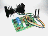
0-30 VDC Stabilized power supply with current control 0.002-3 A

This is a high quality power supply with a continuously variable stabilised output adjustable at any value between 0 and 30VDC. The circuit also incorporates an electronic output current limiter that effectively controls the output current from a few milliamperes (2 mA) to the maximum output of three amperes that the circuit can deliver. This feature makes this power supply indispensable in the experimenters laboratory as it is possible to limit the current to the typical maximum that a circuit under test may require, and power it up then, without any fear that it may be damaged if something goes wrong.
There is also a visual indication that the current limiter is in operation so that you can see at a glance that your circuit is exceeding or not its preset limits.
 
 Technical Specifications - Characteristics

Input Voltage: ................ 24 VAC
Input Current: ................ 3 A (max)
Output Voltage: ............. 0-30 V adjustable
Output Current: ............. 2 mA-3 A adjustable
Output Voltage Ripple: . 0.01 % maximum

FEATURES
- Reduced dimensions, easy construction, simple operation.
- Output voltage easily adjustable.
- Output current limiting with visual indication.
- Complete protection of the supplied device against over loads and malfunction.
 
 How it Works
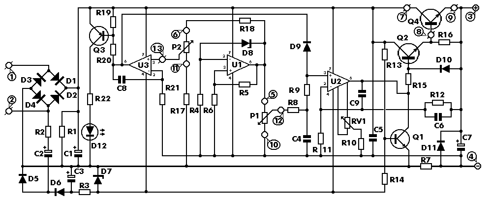
To start with, there is a step-down mains transformer with a secondary winding rated at 24 V/3 A, which is connected across the input points of the circuit at pins 1 & 2. (the quality of the supplies output will be directly proportional to the quality of the transformer). The AC voltage of the transformers secondary winding is rectified by the bridge formed by the four diodes D1-D4. The DC voltage taken across the output of the bridge is smoothed by the filter formed by the reservoir capacitor C1 and the resistor R1. The circuit incorporates some unique features which make it quite different from other power supplies of its class. Instead of using a variable feedback arrangement to control the output voltage, our circuit uses a constant gain amplifier to provide the reference voltage necessary for its stable operation. The reference voltage is generated at the output of U1. The circuit operates as follows: The diode D8 is a 5.6 V zener, which here operates at its zero temperature coefficient current. The voltage in the output of U1 gradually increases till the diode D8 is turned on. When this happens the circuit stabilises and the Zener reference voltage (5.6 V) appears across the resistor R5. The current which flows through the non inverting input of the op-amp is negligible, therefore the same current flows through R5 and R6, and as the two resistors have the same value the voltage across the two of them in series will be exactly twice the voltage across each one. Thus the voltage present at the output of the op-amp (pin 6 of U1) is 11.2 V, twice the zeners reference voltage. The integrated circuit U2 has a constant amplification factor of approximately 3 X, according to the formula A=(R11+R12)/R11, and raises the 11.2 V reference voltage to approximately 33 V. The trimmer RV1 and the resistor R10 are used for the adjustment of the output voltages limits so that it can be reduced to 0 V, despite any value tolerances of the other components in the circuit. Another very important feature of the circuit, is the possibility to preset the maximum output current which can be drawn from the p.s.u., effectively converting it from a constant voltage source to a constant current one. To make this possible the circuit detects the voltage drop across a resistor (R7) which is connected in series with the load. The IC responsible for this function of the circuit is U3. The inverting input of U3 is biased at 0 V via R21. At the same time the non inverting input of the same IC can be adjusted to any voltage by means of P2. Let us assume that for a given output of several volts, P2 is set so that the input of the IC is kept at 1 V. If the load is increased the output voltage will be kept constant by the voltage amplifier section of the circuit and the presence of R7 in series with the output will have a negligible effect because of its low value and because of its location outside the feedback loop of the voltage control circuit. While the load is kept constant and the output voltage is not changed the circuit is stable. If the load is increased so that the voltage drop across R7 is greater than 1 V, IC3 is forced into action and the circuit is shifted into the constant current mode. The output of U3 is coupled to the non inverting input of U2 by D9. U2 is responsible for the voltage control and as U3 is coupled to its input the latter can effectively override its function. What happens is that the voltage across R7 is monitored and is not allowed to increase above the preset value (1 V in our example) by reducing the output voltage of the circuit. This is in effect a means of maintaining the output current constant and is so accurate that it is possible to preset the current limit to as low as 2 mA. The capacitor C8 is there to increase the stability of the circuit. Q3 is used to drive the LED whenever the current limiter is activated in order to provide a visual indication of the limiters operation. In order to make it possible for U2 to control the output voltage down to 0 V, it is necessary to provide a negative supply rail and this is done by means of the circuit around C2 & C3. The same negative supply is also used for U3. As U1 is working under fixed conditions it can be run from the unregulated positive supply rail and the earth. The negative supply rail is produced by a simple voltage pump circuit which is stabilised by means of R3 and D7. In order to avoid uncontrolled situations at shut-down there is a protection circuit built around Q1. As soon as the negative supply rail collapses Q1 removes all drive to the output stage. This in effect brings the output voltage to zero as soon as the AC is removed protecting the circuit and the appliances connected to its output. During normal operation Q1 is kept off by means of R14 but when the negative supply rail collapses the transistor is turned on and brings the output of U2 low. The IC has internal protection and can not be damaged because of this effective short circuiting of its output. It is a great advantage in experimental work to be able to kill the output of a power supply without having to wait for the capacitors to discharge and there is also an added protection because the output of many stabilised power supplies tends to rise instantaneously at switch off with disastrous results.
 Construction

First of all let us consider a few basics in building electronic circuits on a printed circuit board. The board is made of a thin insulating material clad with a thin layer of conductive copper that is shaped in such a way as to form the necessary conductors between the various components of the circuit. The use of a properly designed printed circuit board is very desirable as it speeds construction up considerably and reduces the possibility of making errors. To protect the board during storage from oxidation and assure it gets to you in perfect condition the copper is tinned during manufacturing and covered with a special varnish that protects it from getting oxidised and also makes soldering easier.
Soldering the components to the board is the only way to build your circuit and from the way you do it depends greatly your success or failure. This work is not very difficult and if you stick to a few rules you should have no problems. The soldering iron that you use must be light and its power should not exceed the 25 Watts. The tip should be fine and must be kept clean at all times. For this purpose come very handy specially made sponges that are kept wet and from time to time you can wipe the hot tip on them to remove all the residues that tend to accumulate on it.
DO NOT file or sandpaper a dirty or worn out tip. If the tip cannot be cleaned, replace it. There are many different types of solder in the market and you should choose a good quality one that contains the necessary flux in its core, to assure a perfect joint every time.
DO NOT use soldering flux apart from that which is already included in your solder. Too much flux can cause many problems and is one of the main causes of circuit malfunction. If nevertheless you have to use extra flux, as it is the case when you have to tin copper wires, clean it very thoroughly after you finish your work.
In order to solder a component correctly you should do the following:
- Clean the component leads with a small piece of emery paper.
- Bend them at the correct distance from the components body and insert he component in its place on the board.
- You may find sometimes a component with heavier gauge leads than usual, that are too thick to enter in the holes of the p.c. board. In this case use a mini drill to enlarge the holes slightly. Do not make the holes too large as this is going to make soldering difficult afterwards.
- Take the hot iron and place its tip on the component lead while holding the end of the solder wire at the point where the lead emerges from the board. The iron tip must touch the lead slightly above the p.c. board.
- When the solder starts to melt and flow wait till it covers evenly the area around the hole and the flux boils and gets out from underneath the solder.
- The whole operation should not take more than 5 seconds. Remove the iron and allow the solder to cool naturally without blowing on it or moving the component. If everything was done properly the surface of the joint must have a bright metallic finish and its edges should be smoothly ended on the component lead and the board track. If the solder looks dull, cracked, or has the shape of a blob then you have made a dry joint and you should remove the solder (with a pump, or a solder wick) and redo it. Take care not to overheat the tracks as it is very easy to lift them from the board and break them.
- When you are soldering a sensitive component it is good practice to hold the lead from the component side of the board with a pair of long-nose pliers to divert any heat that could possibly damage the component.
- Make sure that you do not use more solder than it is necessary as you are running the risk of short-circuiting adjacent tracks on the board, especially if they are very close together.
- When you finish your work, cut off the excess of the component leads and clean the board thoroughly with a suitable solvent to remove all flux residues that may still remain on it.

connections
 (12,5cm x 8,7cm)
layout.

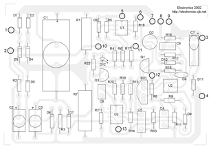
As it is recommended start working by identifying the components and separating them in groups. Place first of all the sockets for the ICs and the pins for the external connections and solder them in their places. Continue with the resistors. Remember to mound R7 at a certain distance from the printed circuit board as it tends to become quite hot, especially when the circuit is supplying heavy currents, and this could possibly damage the board. It is also advisable to mount R1 at a certain distance from the surface of the PCB as well. Continue with the capacitors observing the polarity of the electrolytic and finally solder in place the diodes and the transistors taking care not to overheat them and being at the same time very careful to align them correctly.
Mount the power transistor on the heatsink. To do this follow the diagram and remember to use the mica insulator between the transistor body and the heatsink and the special fibber washers to insulate the screws from the heatsink. Remember to place the soldering tag on one of the screws from the side of the transistor body, this is going to be used as the collector lead of the transistor. Use a little amount of Heat Transfer Compound between the transistor and the heatsink to ensure the maximum transfer of heat between them, and tighten the screws as far as they will go.
Attach a piece of insulated wire to each lead taking care to make very good joints as the current that flows in this part of the circuit is quite heavy, especially between the emitter and the collector of the transistor.
It is convenient to know where you are going to place every thing inside the case that is going to accommodate your power supply, in order to calculate the length of the wires to use between the PCB and the potentiometers, the power transistor and for the input and output connections to the circuit. (It does not really matter if the wires are longer but it makes a much neater project if the wires are trimmed at exactly the length necessary).
Connect the potentiometers, the LED and the power transistor and attach two pairs of leads for the input and output connections. Make sure that you follow the circuit diagram very care fully for these connections as there are 15 external connections to the circuit in total and if you make a mistake it may be very difficult to find it afterwards. It is a good idea to use cables of different colours in order to make trouble shooting easier.
The external connections are:
- 1 & 2 AC input, the secondary of the transformer.
- 3 (+) & 4 (-) DC output.
- 5, 10 & 12 to P1.
- 6, 11 & 13 to P2.
- 7 (E), 8 (B), 9 (E) to the power transistor Q4.
- The LED should also be placed on the front panel of the case where it is always visible but the pins where it is connected at are not numbered.

When all the external connections have been finished make a very careful inspection of the board and clean it to remove soldering flux residues. Make sure that there are no bridges that may short circuit adjacent tracks and if everything seems to be all right connect the input of the circuit with the secondary of a suitable mains transformer. Connect a voltmeter across the output of the circuit and the primary of the transformer to the mains.
DO NOT TOUCH ANY PART OF THE CIRCUIT WHILE IT IS UNDER POWER.
The voltmeter should measure a voltage between 0 and 30 VDC depending on the setting of P1, and should follow any changes of this setting to indicate that the variable voltage control is working properly. Turning P2 counter-clockwise should turn the LED on, indicating that the current limiter is in operation.


 Adjustments

If you want the output of your supply to be adjustable between 0 and 30 V you should adjust RV1 to make sure that when P1 is at its minimum setting the output of the supply is exactly 0 V. As it is not possible to measure very small values with a conventional panel meter it is better to use a digital meter for this adjustment, and to set it at a very low scale to increase its sensitivity.
 

 Warning

While using electrical parts, handle power supply and equipment with great care, following safety standards as described by international specs and regulations.
CAUTION
This circuit works off the mains and there are 220 VAC present in some of its parts.
Voltages above 50 V are DANGEROUS and could even be LETHAL.
In order to avoid accidents that could be fatal to you or members of your family please observe the following rules:
- DO NOT work if you are tired or in a hurry, double check every thing before connecting your circuit to the mains and be ready
- to disconnect it if something looks wrong.
- DO NOT touch any part of the circuit when it is under power.
- DO NOT leave mains leads exposed. All mains leads should be well insulated.
- DO NOT change the fuses with others of higher rating or replace them with wire or aluminium foil.
- DO NOT work with wet hands.
- If you are wearing a chain, necklace or anything that may be hanging and touch an exposed part of the circuit BE CAREFUL.
- ALWAYS use a proper mains lead with the correct plug and earth your circuit properly.
- If the case of your project is made of metal make sure that it is properly earthen.
- If it is possible use a mains transformer with a 1:1 ratio to isolate your circuit from the mains.
- When you are testing a circuit that works off the mains wear shoes with rubber soles, stand on dry non conductive floor
- and keep one hand in your pocket or behind your back.

- If you take all the above precautions you are reducing the
- risks you are taking to a minimum and this way you are protecting
- yourself and those around you.
- A carefully built and well insulated device does not constitute any danger for its user.
- BEWARE: ELECTRICITY CAN KILL IF YOU ARE NOT CAREFUL.
 

 If it does not work

Check your work for possible dry joints, bridges across adjacent tracks or soldering flux residues that usually cause problems.
Check again all the external connections to and from the circuit to see if there is a mistake there.
- See that there are no components missing or inserted in the wrong places.
- Make sure that all the polarised components have been soldered the right way round. - Make sure the supply has the correct voltage and is connected the right way round to your circuit.
- Check your project for faulty or damaged components.
 

 Electronic Diagram.


Parts List.

R1 = 2,2 KOhm 1W
R2 = 82 Ohm 1/4W
R3 = 220 Ohm 1/4W
R4 = 4,7 KOhm 1/4W
R5, R6, R13, R20, R21 = 10 KOhm 1/4W
R7 = 0,47 Ohm 5W
R8, R11 = 27 KOhm 1/4W
R9, R19 = 2,2 KOhm 1/4W
R10 = 270 KOhm 1/4W
R12, R18 = 56KOhm 1/4W
R14 = 1,5 KOhm 1/4W
R15, R16 = 1 KOhm 1/4W
R17 = 33 Ohm 1/4W
R22 = 3,9 KOhm 1/4W
RV1 = 100K trimmer
P1, P2 = 10KOhm  linear pontesiometer
C1 = 3300 uF/50V electrolytic
C2, C3 = 47uF/50V electrolytic
C4 = 100nF polyester
C5 = 200nF polyester
C6 = 100pF ceramic
C7 = 10uF/50V electrolytic
C8 = 330pF ceramic
C9 = 100pF ceramic
D1, D2, D3, D4 = 1N5402,3,4 diode 2A - RAX GI837U
D5, D6 = 1N4148
D7, D8 = 5,6V Zener
D9, D10 = 1N4148
D11 = 1N4001 diode 1A
Q1 = BC548, NPN transistor or BC547
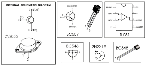
Q2 = 2N2219 NPN transistor
Q3 = BC557, PNP transistor or BC327
Q4 = 2N3055 NPN power transistor
U1, U2, U3 = TL081, operational amplifier
D12 = LED diode
Read More

Discrete Virtual Ground Circuit Diagram

Here is the simple virtual ground circuit based on discrete components. This simple design comes from miniaturization guru Sijosae. Is to make a buffer from generic discrete components. The transistors can be most any complementary pair of small-signal transistors. Suitable alternatives are the PN2222A and PN2907A. The diodes are generic small-signal types. An acceptable alternative is the 1N914. This circuit has better performance than a simple resistive divider virtual ground, and the parts cost is lower than for any other circuit mentioned here. It is, however, the least accurate of the buffered virtual ground circuits.

Discrete Virtual Ground Circuit Diagram


Discrete Virtual Ground Circuit Diagram 

 Parts:

R1,R2 = 4.7K
R3,R4 = 4.7R
C1,C2 = 470uF-25V
C3,C4 = 47uF-25V
D1,D2 = 1N4148
Q1 = 2SC1384
Q2 = 2SA684
B1 = Battery
Read More

Stabilized Regulated Power Supply Circuit Diagram

This circuit of power supply, is very simple and easy to built, it can be assembled on a general-purpose PCB, finding its materials is very easy and cost-small. The output voltage is stabilized and is regulated in the region from 0V until + 15V dc, with biggest provided current 1 A. The regulation becomes with the P1. The Q1 is classic power transistor and it needs to be placed on a cool rib (Heatsink), when it works continuously in the region of biggest current it gets hot. The type of transformer is standard in the market.

Circuit diagram:


Stabilized Power Supply Circuit Diagram


Parts:

P1 = 330R-Potentiometer
R1 = 560R-2W
C1 = 2200uF-35V
C2 = 100uF-35V
C3 = 10uF-25V
C4 = 220uF-25V
C5 = 100nF-63V
D1 = 18V-1.5W Zener
Q1 = 2N3055 NPN Transistor
T1 = 220VAC – 18V@ 1.5A
BR1 = 4x1N4007 Diode Bridge
SW1 = Mains On-Off Switch
Read More

Micropower Voltage Regulator Circuit Diagram

This circuit was developed to power an AVR microcontroller from a 12 V lead-acid battery. The regulator itself draws only 14 µA. Of course, there are dedicated ICs, for example from Linear Technology or Maxim, which can be used, but these can be very hard to get hold of and are frequently only available in SMD packages these days. These difficulties are simply and quickly avoided using this discrete circuit.

Micropower Voltage Regulator Circuit diagram :


The series regulator component is the widely-available type BS170 FET. When power is applied it is driven on via R1. When the output voltage reaches 5.1 V, T2 starts to conduct and limits any further rise in the output voltage by pulling down the voltage on the gate of T1. The output voltage can be calculated as follows:

UOUT = (ULED + UBE) × (R4 + R2) / R4
where we can set ULED at 1.6 V and UBE at 0.5 V. The temperature coefficients of ULED and UBE can also be incorporated into the formula. The circuit is so simple that of course someone has thought of it before. The author’s efforts have turned up an example in a collection of reference circuits dating from 1967: the example is very similar to this circuit, although it used germanium transistors and of course there was no FET. The voltage reference was a Zener diode, and the circuit was designed for currents of up to 10 A. Perhaps our readers will be able to find even earlier examples of two-transistor regulators using this principle?
Read More

Single-cell Power Supply Circuit Diagram

Many modern electronic devices and micro-controller based circuits need a 5 V or 3.3 V power  supply. It is important  that  these voltages are constant and so a regulator of some kind is essential, including in battery powered devices. The simplest approach is to select a (perhaps rechargeable) battery whose voltage is rather higher than that required by the circuit and use an ordinary  linear voltage regulator. Unfortunately this solution is rather wasteful of precious energy and space: for a 5 V circuit at least six NiCd or NiMH cells would be required.

Both these disadvantages can be tackled using a little modern electronics. A good way to minimise energy losses is to use a switching regulator, and if we use a regulator with a step-up topology then we can simultaneously reduce the number of cells needed to power the circuit. Fortunately it is not too difficult to design a step-up converter suitable for use in portable equipment as the semi-conductor manufacturers make a wide range of devices aimed at exactly this kind of application. The Maxim MAX1708 is one example. It is capable of accepting an input voltage anywhere in the range from 0.7 V to 5 V, and with the help of just five external capacitors, one resistor, a diode and a coil, can generate a fixed output voltage of 3.3 V or 5 V. With two extra resistors the output voltage can be set to any desired value between 2.5 V  and 5.5 V. 

Single-cell Power Supply Circuit diagram :


Characteristics
  • Input voltage from 0.7 V to 5 V
  • Output voltage from 2.5 V to 5.5
  • Maximum output current 2 A
  • Can run from a single cell
The technical details of this integrated circuit can be  found on the manufacturer’s website [1], and the full datasheet is available for download. An important feature of  the device is that it includes an internal reference and integrated power switching MOSFET, capable of handling currents of up to 5 A. It is, for example, possible to convert 2 V at  5 A at the input to the circuit into 5 V at 2 A at the output, making it feasible to build a 5 V regulated supply powered from just two NiCd  or NiMH cells. With a single cell the maximum possible current at 5 V would  be reduced to around 1 A.

The example circuit shown here is configured for an output voltage of 5 V. The capacitor connected to pin 7 of the IC  enables the ‘soft start’ feature. R2 provides current limiting  at slightly more than 1 A. For maximum output current R2  can be dispensed with. Pins 1 and 2 are control inputs that allow the device to be shut down. To configure the device  for 3.3 V output, simply connect pin 15 to ground.

The coil and diode need to be selected carefully, and depend on the required current output. To minimise  losses D1 must be a Schottky type: for a 1A output current the SB140 is a suitable choice.

For L1 a fixed power inductor, for example from the Fastron PISR series, is needed. A fundamental limitation of the step-up converter is that the input voltage must be lower than the output voltage. For example, it is not possible to use a  3.7 V  lithium-polymer cell (with a terminal voltage of 4.1 V fully charged) at the input and expect to be able to generate a 3.3 V output, as diode D1 would  be  permanently conducting. On the other hand, there is no difficulty in generating a 5 V  output from a lithium-polymer cell.


Sourced By: Link
Read More