A circuit for monitoring the status of the battery and generator is undoubtedly a good idea for motorcyclists, as for other motorists. However, not every biker is willing to drill the necessary holes in the cockpit for the usual LED lamps, or to screw on an analogue accessory instrument. The circuit shown here manages to do its job with a single 5-mm LED, which can indicate a total of six different conditions of the onboard electrical system. This is done using a dual LED that can be operated in pulsed or continuous mode (even in daylight). Built on a small piece of prototyping board and fitted in a mini-enclosure, the complete circuit can be tucked inside the headlamp housing or hidden underneath the tank.
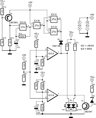
The heart of the circuit is IC2, a dual comparator. The comparator circuit is built without using any feedback resistors, with the indication being stabilised by capacitors C4 and C5 instead of hysteresis. Small 10-µF tantalum capacitors work well here; 220-µF ‘standard’ electrolytic capacitors are only necessary with poorly regulated generators. Voltage regulator IC1 provides the reference voltage for IC2 via voltage divider R2/R3. The onboard voltage is compared with the reference voltage via voltage dividers R4 /R5 and R6/R7, which are connected to the inverting and non-inverting comparator sections, respectively.
Using separate dividers allows the threshold levels to be easily modified by adjusting the values of the lower resistors. IC2a drives the anode of the red diode of LED D4 via pull-up resistor R10. The anode of the green diode is driven by IC2b and R11. T2 pulls R11 to ground, thereby diverting the operating current of the green diode of the LED, if the voltage of the electrical system exceeds a threshold level of 15 V (provided by Zener diode D3). The paralleled gate outputs on pins 10 and 11 of IC3 perform a similar task. However, these gates have internal current limiting, so they can only divert a portion of the current from the red diode of the LED.

The amount of current diverted depends on the battery voltage. The two gates are driven by an oscillator built around IC3a, which is enabled via voltage divider R14/R15 and transistor T1 when the battery voltage is sufficiently high. Depending on the state of IC3a, the red diode of the LED blinks or pulses. The circuit is connected to the electrical system via fuse F1 and a low-pass filter formed by L1 and C1. If you cannot obtain a low-resistance choke, a 1-Ω resistor can be used instead. In this case, the values of C3, C4 and C5 should be increased some-what, in order to help stabilise the indication. D1 protects the circuit against negative voltage spikes, as well as offering protection against reverse-polarity connection. Due to its low current consumption (less than 30 mA), the circuit could be connected directly to the battery, but it is better to power it from the switched positive voltage.
The amount of current diverted depends on the battery voltage. The two gates are driven by an oscillator built around IC3a, which is enabled via voltage divider R14/R15 and transistor T1 when the battery voltage is sufficiently high. Depending on the state of IC3a, the red diode of the LED blinks or pulses. The circuit is connected to the electrical system via fuse F1 and a low-pass filter formed by L1 and C1. If you cannot obtain a low-resistance choke, a 1-Ω resistor can be used instead. In this case, the values of C3, C4 and C5 should be increased some-what, in order to help stabilise the indication. D1 protects the circuit against negative voltage spikes, as well as offering protection against reverse-polarity connection. Due to its low current consumption (less than 30 mA), the circuit could be connected directly to the battery, but it is better to power it from the switched positive voltage.


0 comments:
Post a Comment