
This wireless baby monitor circuit using FM is designed to operate at a frequency of 100MHzefy tested. Its range of transmission is more than 100 metres with a 75cm wire antenna. The circuit is fully transistorised and so even a beginner can easily assemble it on a veroboard or the PCB whose pattern is given below for convenience.
Simple Wireless Baby Monitor Project

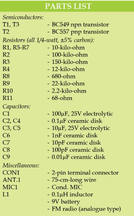
Circuit diagram of the wireless baby monitor circuit is shown in Fig. 1. It is built around a condenser microphone (MIC1), transistors BC549 (T1 and T3) and BC557 (T2), along with a few other components.
T1 and T2 provide high-gain audio to the VHF oscillator wired around T3. BC549 can oscillate well in VHF range. Frequency-modulated (FM) signals are transmitted through antenna ANT.1.
By adjusting trimmer capacitor VC1, frequency can be set within 88MHz -108MHz band. Using a good FM radio (analogue type) receiver, transmitted signals can be heard. Do not use a mobile phone as receiver.
This unit with 9-volt battery can be kept near a baby’s bed. Any sound generated by the baby including a cry can be monitored wirelessly from another room. Readily available 1-micro Henry inductor can be used as L1. It can also be home brewed as shown in Fig. 2.

Construction and testing

A single side PCB pattern of the wireless baby monitor circuit is shown in Fig. 3 and its component layout in Fig. 4. After assembling the circuit on a PCB, enclose it in a plastic case and keep it near the baby’s bed.


0 comments:
Post a Comment